


Alignment of Rotating Machines

Definition of misalignment
Alignment refers to the adjustment of machine bases when the machine is at rest, so that during normal operation, the rotating axes of coupled machines are aligned. While leveling machines or adjusting couplings is important, it is not alignment! In alignment, the goal is to bring the rotating axes of the machines into alignment without considering the coupling or whether they are horizontally or vertically level.
As illustrated, each misalignment consists of two components of offset (horizontal and vertical) and two components of angular deviation (horizontal and vertical). In alignment operations, all four components must be measured and corrected to reduce the resultant misalignment to an acceptable level.

Common Alignment Methods
1. Use of Bars and Shims:
This is the simplest alignment method, typically used for simple and low-speed machines. Errors in this method can create significant vibration problems. This method essentially aligns two couplings, and any eccentricity, roughness, diameter disparity between the two halves, and machining errors in the coupling will lead to inaccuracies. In the best-case scenario, the accuracy of this method can reach up to 0.1 millimeters. This method can be used for simple and low-speed machines and for initial alignment.

2. Use of Dial Indicators:
Experienced machine installers still use dial indicators for the installation of critical machinery. There are several methods for using this tool, each with its own unique features. However, these methods can also contain latent errors that may remain hidden even from experienced practitioners. With this tool, an accuracy of up to 0.01 millimeters can be achieved in optimal conditions, which is sufficient for the majority of machines. The common methods of using dial indicators are illustrated in the image.

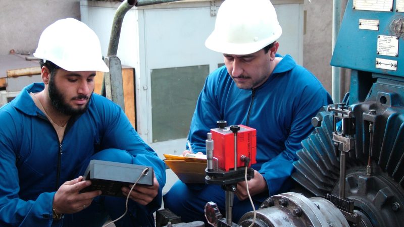
3. Use of Laser Methods:
Laser optical equipment has significantly enhanced the speed, accuracy, and ease of traditional alignment operations. In maintenance processes and major overhaul cycles, repair operations not only incur repair costs but also cause significant productivity losses due to machine downtime. Alignment operations can take a substantial part of machine downtime. Laser equipment, besides increasing accuracy and eliminating typical errors of traditional methods, can reduce alignment time to a quarter of the usual duration.
Today, laser equipment has been developed for various types of alignment, including:
-
-
Straightness
-
Flatness
-
Center of Bearing
-
Parallelism
-
Normality
-
Pointing Direction
-
Online Alignment (PermAlign)
-

Other Specific Methods:
For many specialized machines, specialized methods may be required, including:
-
Using cords or wires for aligning pulleys.
-
Using piano wire for aligning bearings with large distances, such as in ships or turbines.
-
Employing precise surveying cameras for leveling in large machines.
Reference
books
download software
Current seminars
Scientific and research
town of Isfahan
Vibration Training
Guide to training courses
educational calendar
services
condition monitoring
Field Balancing
Shop Balancing
Machinery Alignment
Vibration Labratoary
products
VB95 vibro balancer
Payande software
VM4-96 system
VM4 monitor
VM4-96-p monitor
monitoring software
cabin balance 93
ROD
CAL-401
Stroboscope
BNC box
conectors and cable
![]()